In this episode of yak shaving, I will talk about how I spent a week setting up the E3D tool changer. I was working on the week #1 update for the Aeroh Link Crowdfunding campaign. I received one key piece of feedback: customers would prefer color options rather than the standard color option, i.e., Yellow. Ideally, a Black and a White option will be preferable because most home appliances are either black or white. So, I wanted to print enclosures with those color options and post an update about it.
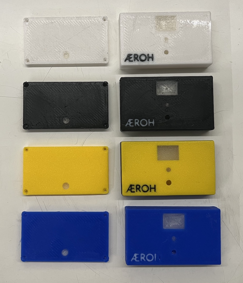
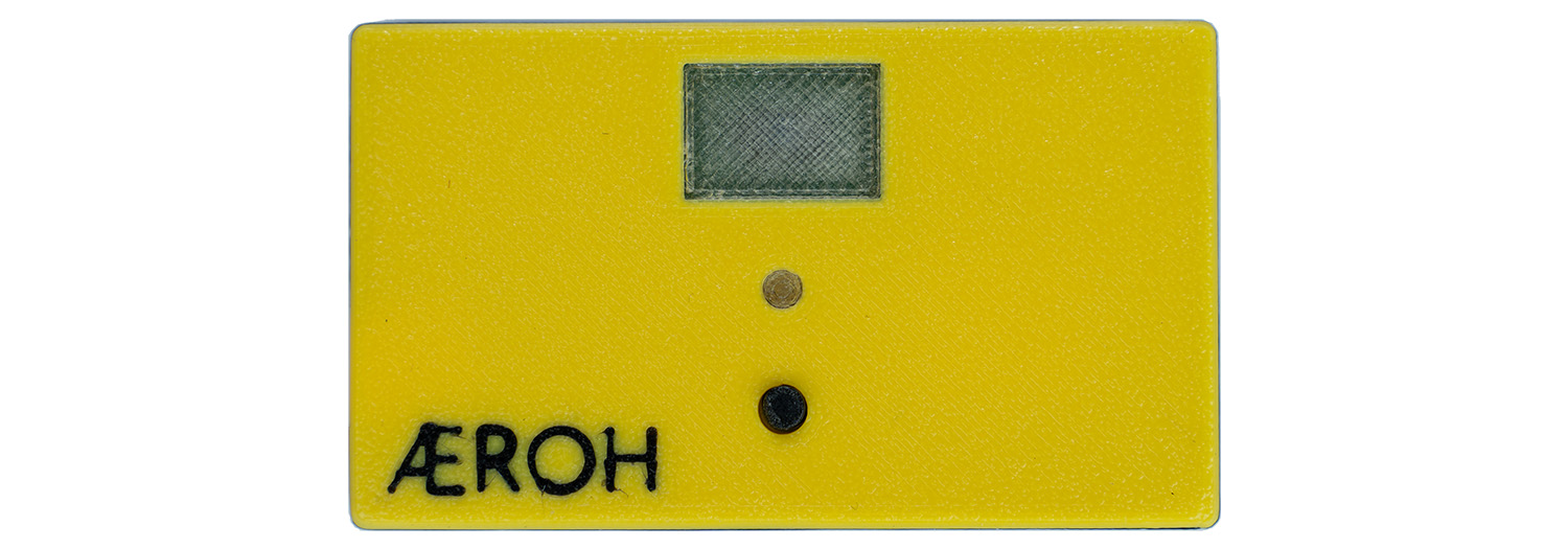
The Aeroh Link enclosure is a multi-color print. It is composed of a minimum of three colors:
- Primary (Yellow, Black, or White)
- Lens (Transparent)
- Contract Color (For Logo)
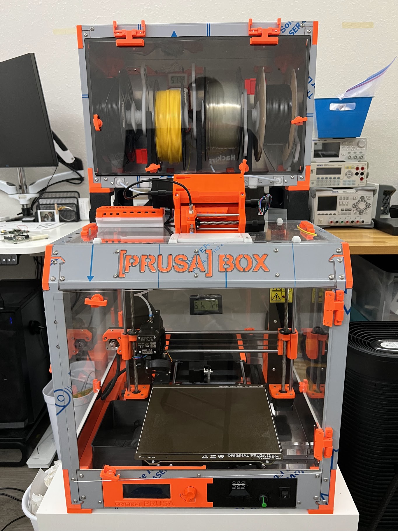
I used to print these with a Prusa i3 MK3S+ with an MMU (Multi-Material Unit) unit on. Prusa i3s are reliable machines. But with an MMU unit on (MMU2S, to be more specific), it’s another story. That is probably why Prusa introduced their latest printer Prusa XL with a Tool Changer instead of an MMU unit. But, Good Luck buying a Prusa XL, because even though it was announced in November 2021, they are running into supply chain issues and are expected to ship by the end of 2023. I can’t wait that long. But I digress; Prusa with MMU2S is a nightmare to use. That is because it relies on switching filament whenever it wants to change filament. In the worst-case scenario, it will change the filament on every layer with all color options. And the process of filament changing is not very reliable. If the filament tip forms a blob while it’s being taken out, it will jam during retraction or loading. So, you have to babysit the printer while printing multi-material prints. It’s not a great experience! Prusa also released MMU3 a few days back, but if you respect your time, I think it’s not worth dealing with MMU at all.
So, I decided to upgrade. Get something with a Tool Changer, and say goodbye to MMU-based systems. And I purchased an E3D Tool Changer back in Nov 2022. But I didn’t commission it yet — meaning, I assembled it but haven’t gotten around to setting up the software and calibrating the printer. In this post, I will cover the challenges I faced while commissioning the printer, mainly the EMI issue, as I have never expected or faced such an issue in any other printer, and how I built a workaround for it.
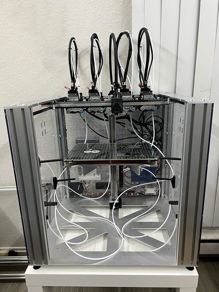
E3D Tool Changer is not a perfect printer — at least not out of the box, for two reasons:
- The printer setup documentation is not great. E3D says it’s a research platform, but that’s not a good reason to cut down on documentation to get the first prints right.
- I encountered several QA issues while building the printer.
I got an E3D Tool Changer with 4 x Hemera Direct Extruders, and here are a few issues I faced while setting up the printer.
Aluminum Extrusions Weren’t Tapped
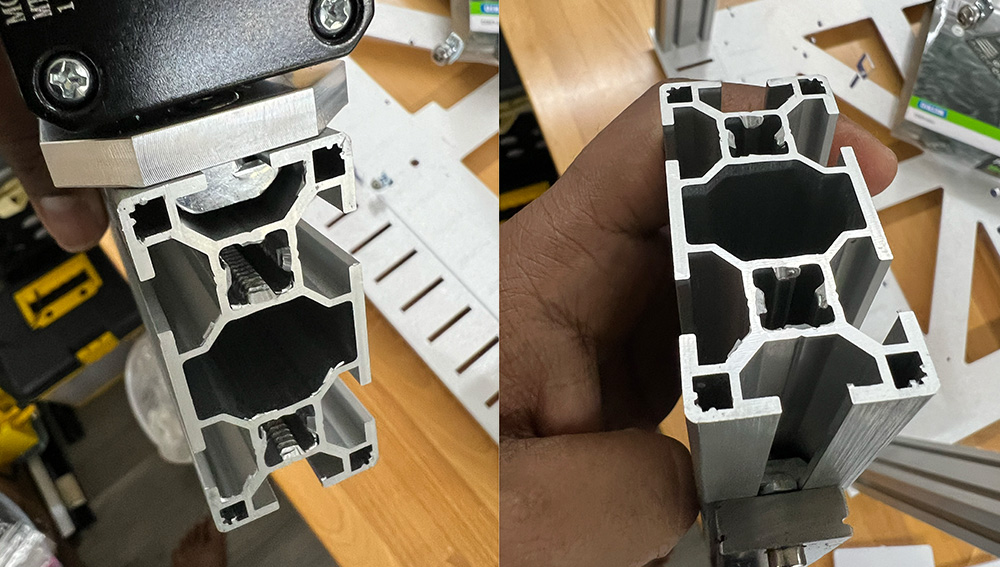 Left: Tapped Bottom Side. Right: Untapped Top Side
The Tool Changer has 5 60×30 Aluminum Extrusions. All these extrusions should be tapped on both ends for two M6 screws on each end. One of the Aluminum Extrusions; the one with the Linear Rail for the Z-Axis, wasn’t tapped on the top side, so the M6 screw wasn’t going in. I had to buy 💸 a tapping kit, and I had to tap it myself.
The motor Cables were too Short.
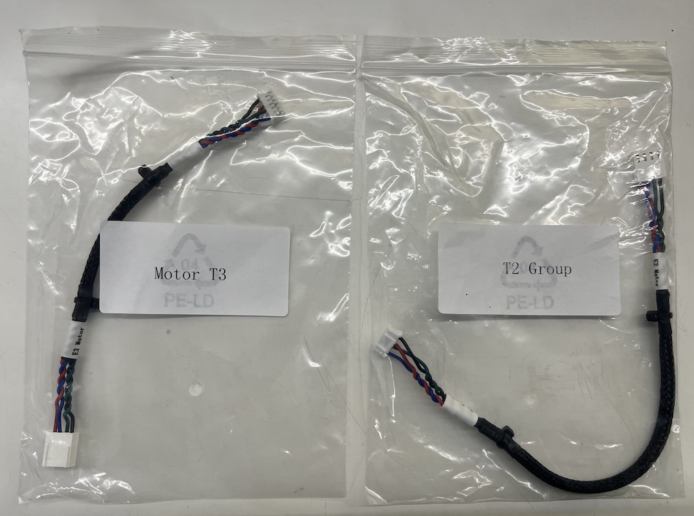
I got a Hemera Direct Extruder version, not the Hemera Bowden version. The Direct Extruder mounts directly on the tool head. So, I needed a longer motor cable to connect the extruder motor to the controller board. But my printer came with shorter cables, which appear to be for the Bowden setup and not the direct extruder setup. I had to make 💸 cable extensions for them.
Update (Apr 7, 2023): @wstallwood on Discord mentioned that the kit includes four tiny PCB connectors and four stepper motor cables with Hemera that can extend the Bowden cables. Not very elegant, but this could have saved me time.
I got the wrong PSU
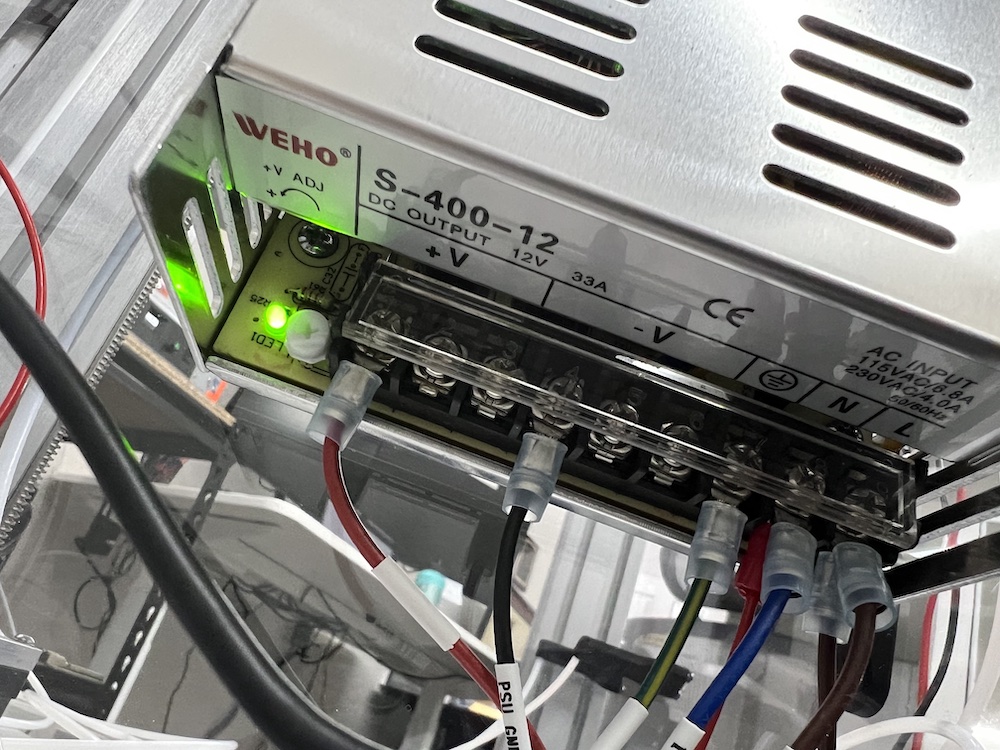
E3D Tool Changer is a 24V system, and I should have received a 24V Power Supply Unit (PSU). But I received a 12V PSU. I created a support ticket for a replacement and have yet to hear back from E3D. For now, I swapped 💸 it with another 24V PSU from my Pick and Place machine.
Update (Apr 10, 2023): Georgia from E3D reached out and said they responded to my support ticket on March 30th and shared a screenshot. So, I did a bit of digging and found the email in my spam folder. They asked for some information about the work order and batch number. I shared what I have and waiting for a response.
Standard Config doesn’t support Direct Extruders.
The standard config from E3D is not built for Direct Extruder systems. It’s built for Bowden System. So there are issues. I thought the problems would primarily be around extruder position (offsets). But the bigger problem was with the max speeds and accelerations. I broke the end stop because of this; more on that in the next section. I later reduced the max feed rate from 50000 to 5000, which worked. Someone on E3D Discord told me the Direct Extruder system could not accelerate as fast as the Bowden system, so it skips steps, so he had to reduce the max speeds and accelerations with M203 and M201 Commands. I am yet to try out that approach.
I also ran into a few other issues with the config:
- Hemera uses a different value for E steps per mm — fix.
- Extruder T0 and T1 rotate in the opposite direction — fix.
- Tool Head Collides on the X-axis when pausing the print — fix.
- I also had to update the offsets and positions of tool heads. Your configuration can/will be different.
Here are all the config changes I made to the standard config: https://github.com/aerohstudios/RepRapFirmware-SD/compare/3393b3620615b4e9e0673cc7df2ff5459815aaa7..ffbcd417a9c4bd11299cffafea8c458805cbcf69
Z-Limit Switch will Break.
You can easily break the z-endstop during commissioning. I broke mine once during z-homing, which I fixed somehow, and then broke it for good during mesh leveling. My replacement z-limit switches are on the way. E3D doesn’t have them in stock. I had to purchase the part (Omron D2HW-C211H) from Mouser and hand-solder it myself.
This can happen to anyone. E3D should consider providing at least two spare limit switches with the Tool Changer.
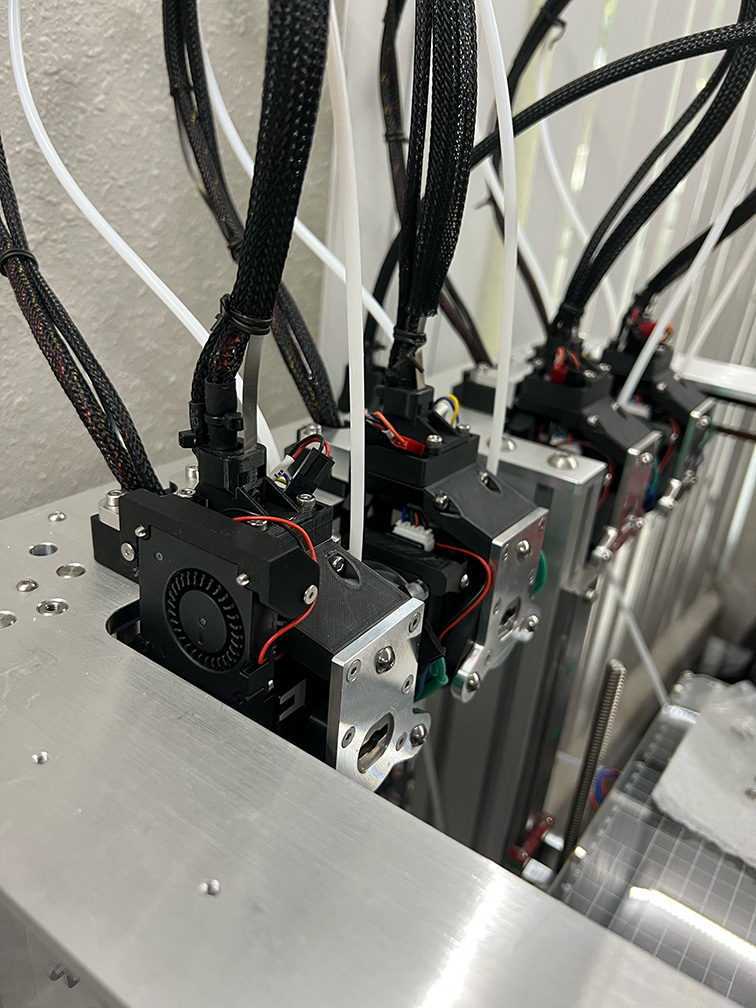
EMI Issue with the Part Cooling Fan
Finally, let’s talk about the EMI issue. The part cooling fan (PCF) is set up directly against the Extruder Motor in the Hemera Direct extruder system. So, it doesn’t work properly when it’s next to the stepper motor. For me, two of the four fans didn’t run at all and made a humming noise, while the other two worked but ran slowly. This seems to be happening because of Electro Magnetic Interference (EMI) from the extruder motor, and a few people on E3D Discord confirmed that it’s a known issue. @Killercds on Discord told me that the older version of GDSTIME works fine without EMI issues. @wstallwood on Discord said he uses a mild-steel washer between the fan and the motor. I tried using stainless steel washers, and they didn’t work. And I don’t have mild steel washers, and I don’t know where to get them here — stores don’t actively advertise that their washers are mild steel 😅 . I tried putting several layers of aluminum foil, and that didn’t work either. @Killercds explained why that didn’t work — we need something ferrous (and magnetic?) to block the EMI. Makes sense.
Anyway, At this point, I decided that I was going to raise the fan. If I can’t block EMI properly, the fan will be slow, resulting in lousy part cooling and bad prints. I had to design three extra parts, and the fan is now raised and runs at full throttle.
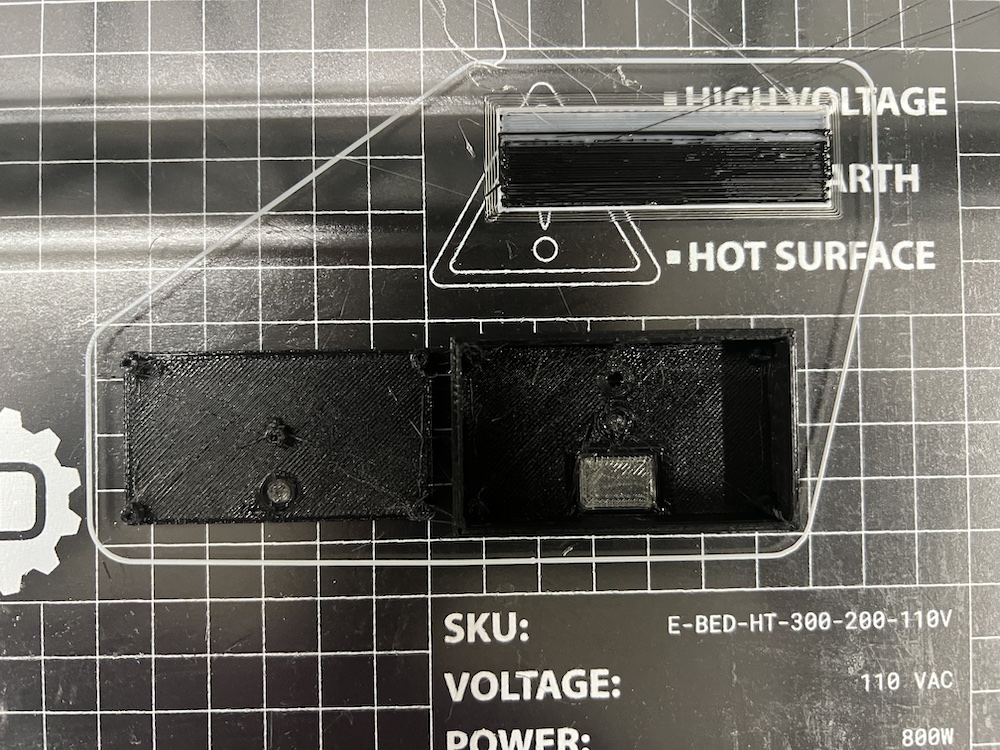
Here are the extra parts that I had to print (for the four extruders)
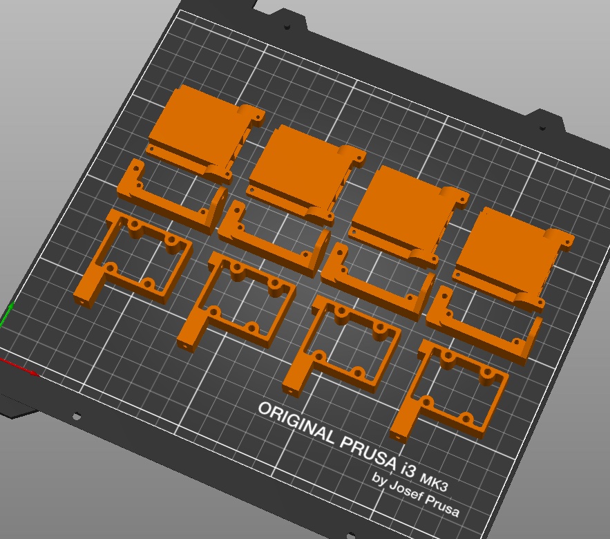
And here are some photos.
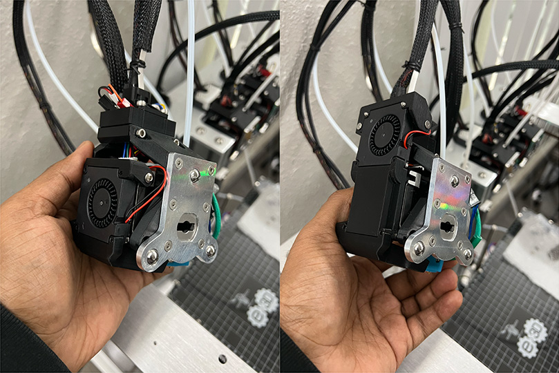
Before the Mod & After the Mod
 The height increase is not significant. So Hopefully, it will not run into any wires.
And here is a video. Play it with sound so you can hear the motor spin at full speed. 😀
If you are interested in using the mod, you can download the files from here:
(Please show your love by liking and rating the model 😃)
Where are the Slicer Settings?
E3D Provides slicer profiles for a few popular slicers. But to my surprise, PrusaSlicer and Cura are missing. Well, they provide SuperSlicer profiles, which is a fork of PrusaSlicer. So, it makes sense to skip PrusaSlicer. But the Super Slicer profile is for ASMBL (Additive & Subtractive Manufacturing By Layer), which is a superset of what I need. I need something simple — 4 extruders that could print PLA, and the SuperSlicer profile is quite verbose. It would have been easier to go through a document explaining the changes I must make to the standard slicer settings to print with E3D Tool Changer. Since that manual is missing, here is my attempt to do that.
Step 1: Create a Custom Printer Profile on Prusa Slicer
You can do this on the latest Prusa Slicer using the following menu option: Configuration > Configuration Assistant.
In the Custom Printer section, you need to enter the following settings:
- Firmware Type: RepRapFirmware
- Bed Shape: Rectangular (x: 300 mm, y: 200 mm)
- Nozzle Diameter: 0.4 mm (default)
- Filament Diameter: 1.75 mm (default)
- Extrusion Temperature: 220 C (for PLA)
- Bed Temperature: 60 C (for PLA)
If you need further assistance, follow this walkthrough video for setting up a custom printer.
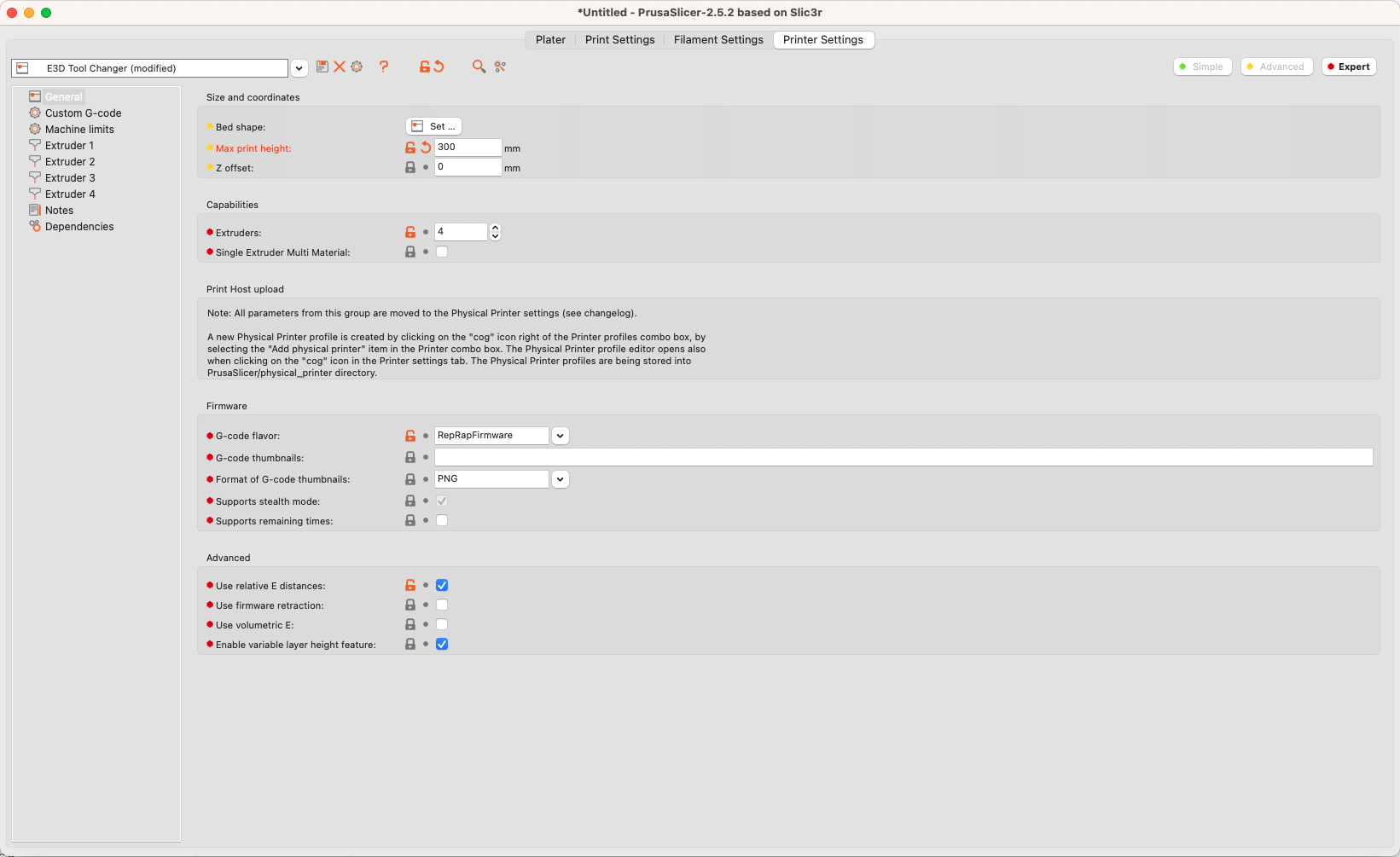
Step 2: Setup 4 Extruders
Under Printer Settings tab, under General side tab make the following changes.
- Extruder: 4
- Use Relative E Distance: Checked
- Max Print Height: 300 mm
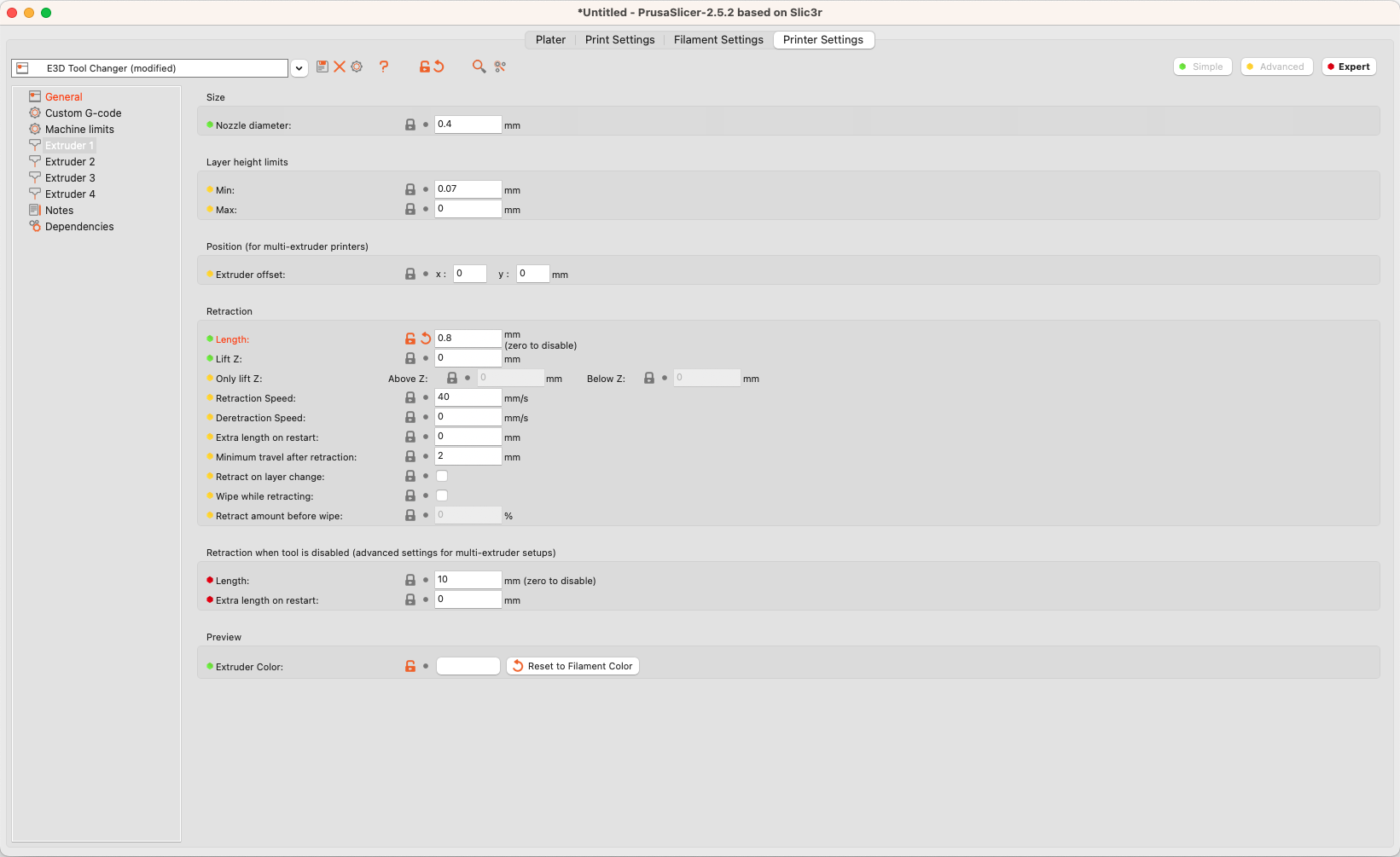
Step 3: Set Retraction Distance
You need a lower retraction distance if you are using Hemera Direct Extruders. Otherwise, your filament will jam.
For each extruder, set a retraction distance of 0.8 mm. My printer was jamming for certain prints with the default 2 mm retraction distance. And, anything lower than 0.8 mm was causing a lot of stringing.
Check out #5 in this E3D knowledge base article.
Optionally, change the Extruder Color to match the filament color.
Step 4: Wipe Tower / Purge Tower
If you are doing a multi-material print, you need a way to clean the nozzle during a nozzle change. Otherwise, the print quality will suffer.
E3D recommends a wiper for this, meaning you must setup up two brass brushes on both sides of the printer. The nozzle will wipe itself before starting the print during a tool change.
However, there is an alternative approach. You can use a Pruge tower. Before starting the print, the nozzle will prime itself on a separate purge block.
 Purge Tower on the Top Right
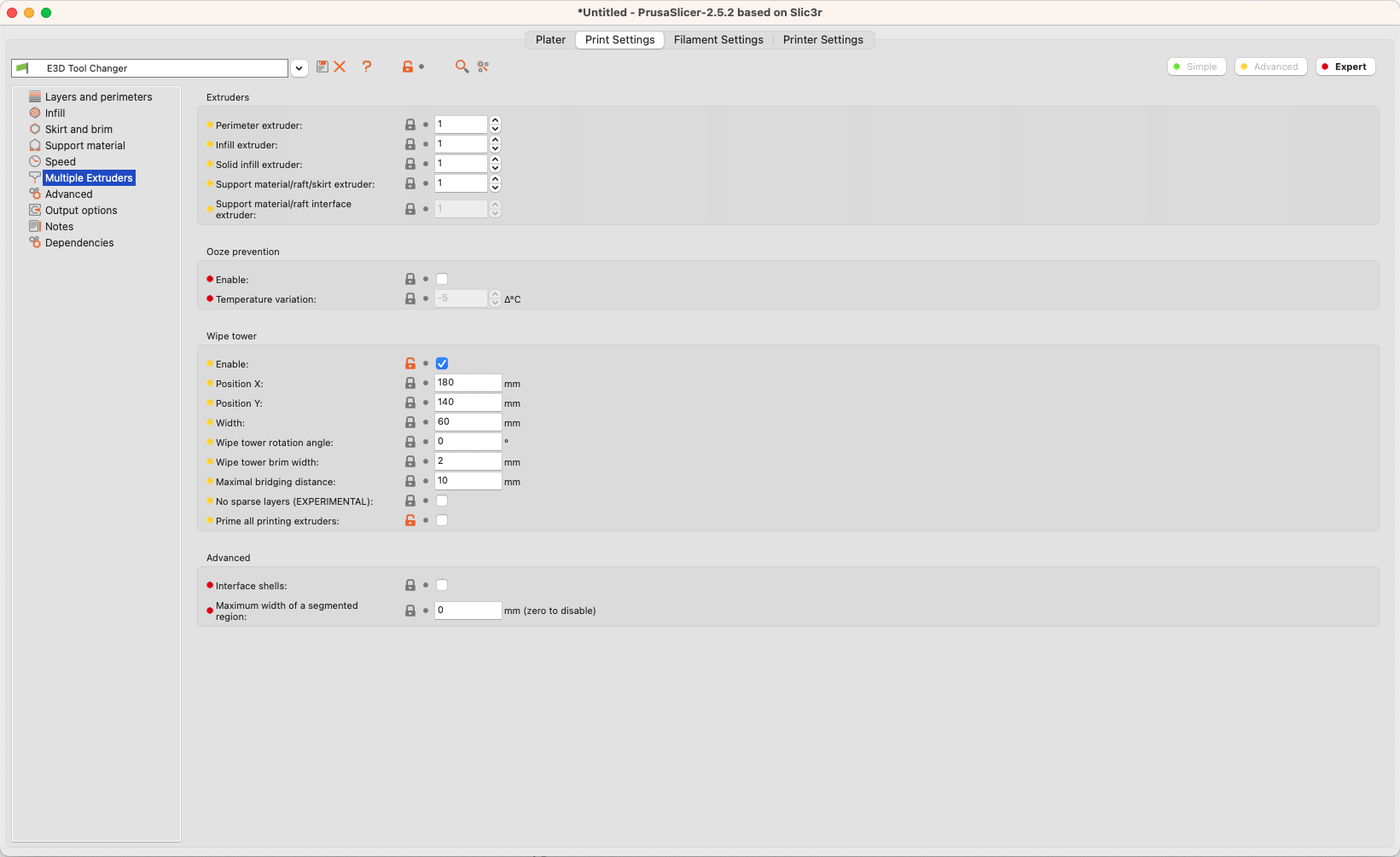
I went with the alternate approach because it’s faster to set up. In the Print Settings tab, under Multiple Extruder side tab,
- enable Wipe Tower, and
- optionally disable Prime all printing extruders
Step 5: Custom G-Codes
You will need custom G-Codes on Start, End, and Tool Change. So, under Printer Settings tab, in Custom G-code side tab, add the following G-code:
Start G-code
T-1;
G28 ; home all axes
G29 S1 ; load height map
G1 Z5 F5000 ; lift nozzle
T0;
End G-Code
; Drop Bed
G91
G1 Z2 F1000
G90

; Drop off the tool
T-1

; Disable Mesh Compensation.
G29 S2


; home X axis
G28 X0


; turn off all heaters
M0
Tool change G-code
T[next_extruder]And you’re all set.
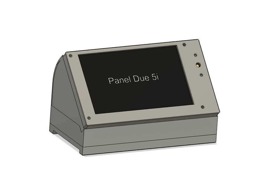
Optional Upgrade: Touch Screen for the E3D Tool Changer
E3D Tool Changer doesn’t have a display/input option. You need to use the web UI to operate the printer. Honestly, that’s not a problem for me. But, I had a Duet3D’s Panel Due 5i, which I was planning to use for a different project, but never got around to. Since the tool changer uses Duet 2 Wifi Controller board, and Panel Due 5i is computable with it, I decided to use it for this printer.
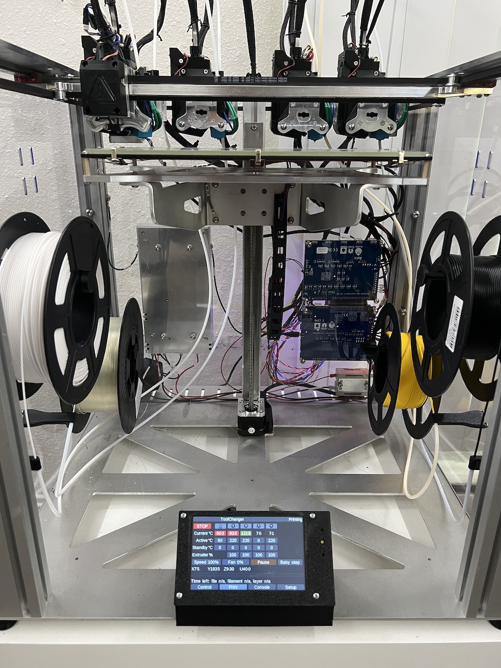
So, I quickly designed a mount for it.
Now, with Panel Due in place, you can use the touch screen to start the prints from the SD card, and you don’t need to go to the web UI.
If you are interested in my Panel Due 5i mount, you can download the files from here:
(Please show your love by liking and rating the model 😃)
Multi Color Prints
A good sign of a successful yak shaving is being able to finish the task you initially started with. For me, it was a white and a black enclosure option for Aeroh Link. After the painstaking effort of configuring E3D Tool Changer, I am happy to report that I can now print as many color options for Aeroh Link as I want.